
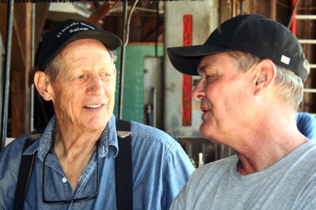
 I stopped by the engine house this morning for a few hours. There wasn't much going on as this is the "off" weekend. In the photo Dave Spohr (left) and Eric Stohl discuss the driveshaft renovation project.
Our Plymouth crew -- Garrett with Ken and sons -- travels up from Sacramento to work on another small piece of Arnold every other weekend. They'll remove one or two of the journal bearings next Saturday.
This morning, Eric Stohl and Dale Mace were installing the final corner brace for the Shay. When I left at 11 a.m., Dale was welding the joint between the base plate and the rod. The brace project will be done once Eric and Dale install the brace.
 Of the six braces, three were completely fabricated by Dale. Only three original braces were found when found when the crew started this project some 12 or 13 years ago. Dale and Eric were able to install two of the original braces without any modification. The third was modified some.
Sam Thompson continued building his valve shaper in the machine shop. Dave Spohr was milling one of the short male drive stafts at the other end of the shop (see photo to left).
The Shay geared locomotive used a line shaft to drive the right wheel on each axel set. ShayLocomotives.com describes this unique arrangement:
These line shafts were attached to square shafts through couplings. The square shafts slid into sleeve shafts, which were attached to the crankshaft through another set of couplings. The square shaft sliding freely in the sleeve shaft allowed the locomotive to take sharp curves. As the truck turned to follow the track curve, the distance between the crankshaft and the truck increased or decreased and the square shaft slid in or out while still rotating, delivering power to the truck from the pistons.
Keith Berry described the restoration process in the spring issue of the newsletter:
Dave [has been working with Sam and Dale since February to restore the male] driveshaft faces to specification. Over normal locomotive operation, surface-to-surface friction from turning and the constant presence of dirt kicked up from the ballast ground the driveshaft faces down.
Sam's challenge was to locate an arbitrary starting surface point to weld/build the contact surfaces and end up with a four-sided square drive shaft. Once established, Dale welds, and Dave mills the surfaces. Then Dale welds, and Dave again mills, and around it goes. Or in this case, square it becomes! Eventually, the shaft will reach finished specification and they'll start on the next shaft.
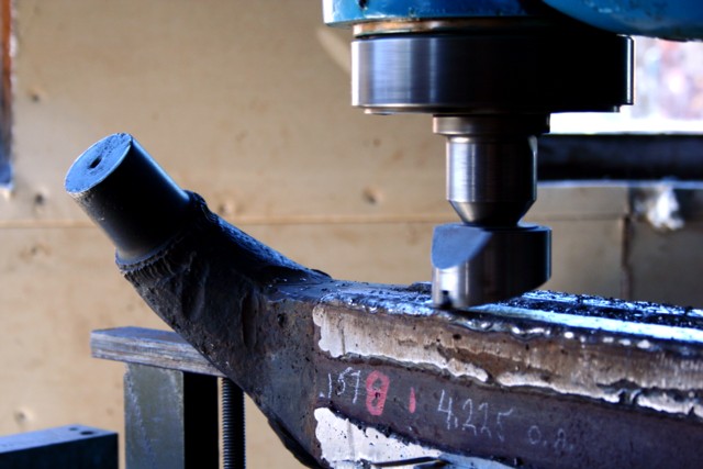 In the photo to the right, Dave used a fly cutter to shave 0.045-inch off the face of the shaft. Dale can only add metal to two surfaces at a time. One of the milled surfaces is used to lay the shaft level on the milling machine. The other is used as a gauge.
Dave feeds the surface being cut at a rate of 3/8-inch per minute. It takes 50 minutes to mill each surface.
Dave said Dale would ultimately add metal to edges so that he could form a true edge on the shaft. The edges take most of the punishment as the shaft slides in and out of the companion driveshaft.

No comments:
Post a Comment